Adding, Naming and Connecting Shapes
This topic describes the basic steps of adding, naming, and connecting shapes in a Triaster process map.
Adding a Shape
To add a shape to a process map, drag it from the stencil and drop it onto the Visio page within the Node.
Naming a Shape
The New dialog box is displayed whenever you add a shape (unless the Don’t show me again check box has been selected in a previous session). This can be used to add the name displayed on the shape and is its identifier in the process map (as used for specifying connections, for example).

NOTE: If the New dialog box does not appear when you add a new shape, you can enable it as follows: right-click on the drawing page, select Options from the popup menu, choose the Tip Windows tab, and then enable Show tip on creation of an <shape>. Alternatively, from the menu tabs in Visio, select Triaster > Options then as above.
The name of the shape needs to be meaningful, informative and short. If the text is too large to fit inside it, adjust the text or resize the shape on the drawing page by selecting it and dragging its coloured ‘handles’. Shape and text size should be in accordance with your Process Governance Framework (if you have one in place).
NOTE: There is a list of forbidden text characters which should be consulted when considering what to name the shape.
You can also edit the name of a shape through its Properties dialog box: right click on the shape and select Properties. Name is the first field on the General tab.


HTML Mouseover Description
You can provide a text description for a shape in the Properties dialog box (see above). This is not displayed in Process Navigator but can be configured to appear as a mouse-over tooltip in the published HTML file. To find out how the description of a shape can be implemented as a mouse-over, please refer to Process Navigator’s Publish to HTML Wizard’s Use description where available option (Step 3).
- Right click on the shape and select Properties. The General tab is displayed.
- Enter text information in the Description box. The Description field is restricted to 252 characters.
- Click on the OK button to close the Properties dialog box.
Commecting Shapes
To add or edit the connectors between shapes such as Activities and Deliverables:
- Right click on the shape and select Properties The General tab is displayed.
- To add a new connection:
- To link an Activity to a Deliverable, select a deliverable from the list in the Available Deliverables box, and then use one of the right arrow buttons to add it to the Inputs or Outputs boxes as required.
- To link a Deliverable to an Activity, select an Activity from the list in the Available Activities box, and then use one of the right arrow buttons to add it to the Suppliers or Customers boxes as required.
- To remove an existing connection, select it and use the appropriate left arrow button to return it to the Available box.
- Repeat as necessary.
- Click on the OK button.
TIP: You can select multiple items by holding down the CTRL key while left-clicking or select a block by holding down the SHIFT key and clicking on the first and last deliverables in the range.
You can also connect activities and deliverables by:
- Dragging the Dynamic Connector shape from the Triaster Process Map stencil and drop it onto the connecting Nodes.
- Selecting the Connector tool on Visio’s Home toolbar and draw the connections from shape to shape. Refer to Visio Help for details.
TIP: Process Navigator interprets any connector as a valid flow, so manually adding connectors is fine provided they are properly glued. When manually adding connectors, they must begin at the right-hand side of the Input and end at the left-hand side of theActivity, or begin at the right-hand side of the Activity and end at the left-hand side of the Output. Process Navigator interprets direction of flow from the direction of connection, so you must be careful to get this right. It is not sufficient to have arrowheads pointing in the right direction because arrowheads can be formatted to go against the flow.
Changing the Connection Points
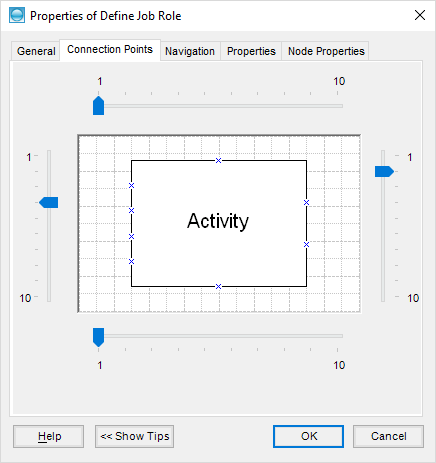
Use the Connection Points tab on a shape’s Properties dialog box to determine the number and placement of its connection points.

- Right click on the shape and select Properties The General tab is displayed.
- Select the Connection Points tab.
- Move the slider on each side of the shape to change the number of connection points. Process Navigator will evenly distribute the connection points along the side of the shape.
- Click on OK to close the dialog box.
NOTE: A maximum of 10 connection points can be selected.
Connector Routings
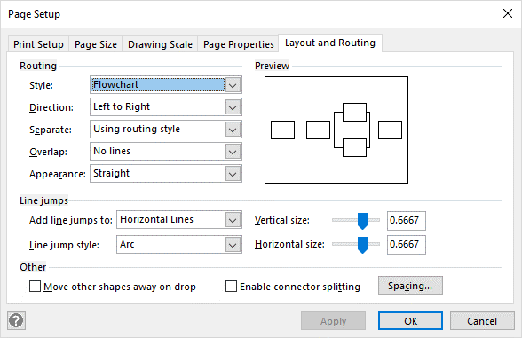
The layout and routing behaviour of connectors can be changed as follows:
- Open a map in Visio.
- On Process Navigator Tools > Page Setup, click on the Layout and Routing tab.
- Configure as required.

Layout and Routing dialog
Changes to these settings will only apply to the current page, and any new pages added; they won't apply to existing pages.